Skip to main contentSkip to navigation
Doctrine · synthetic demonstration

AI-native shipbuilding. A vessel the system can read, and a build it can govern.

What has to agree inside one hull for a vessel to be built and delivered?

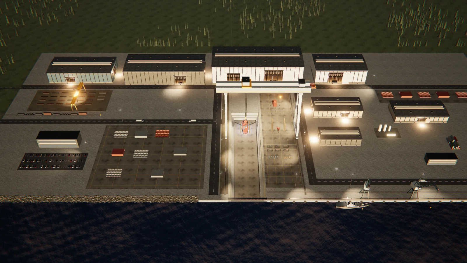
Concept visualization. A shipyard at dusk, the concept hull erected under a gantry crane. Synthetic model; not a Veldarium facility. The vessel's armament is nonfunctional.

A steel part can be cut and welded only when five records agree: its drawing revision, its plate certificate, the weld procedure, a welder qualified to it and the inspection plan. They sit with four departments, and when they disagree the fitter at the block can be the first to know. AI-native is not a model laid over that data. It is a yard built around the agreement: a model proposes from records software can traverse, a named person decides, and machines execute only released work.

Architecture and a synthetic demonstration on a concept vessel. No model of any provider is connected, no yard is operated, and no vessel intelligence is in service.

One vessel, made readable

What does a system have to hold about a vessel before it can help build one?

Every fact that decides whether a part can be built, attached to the part.

Turn the hull, take it apart into blocks and build it stage by stage. Then swap one sensor for a higher-power variant and follow the change through ten hops and six owning disciplines, out of engineering and into the production sequence. Software shaped around one department sees one hop.

The vessel, in three dimensions

Turn it, take it apart, build it, change one drawing.

synthetic · schematic
VS-001, schematic profile, the drawing the 3D model is lofted fromArmament is shown as nonfunctional exterior equipment in a concept, for visual communication. No weapon system is selected, integrated or approved, and no capability, quantity, firing arc or ammunition arrangement is implied. Topside areas are reserved volumes in a concept. No sensor, communications, aircraft or vehicle-handling system is selected, designed, integrated or approved.

Synthetic · not an engineered design

The drawing below is the same vessel the 3D model shows.

VS-001, a synthetic concept of 50 m, lofted from the site's profile drawing.

Breadth and section form are drawing choices. The beam is not claimed. Its waterline is the drawing's, not a computed draft; displacement and classification are not claimed. The vessel's armament is nonfunctional. Topside areas are reserved volumes in a concept.

Design basis: what this hull is and is not; 12 of 12 geometry checks pass

Drawing decisions

Drawn as a modular uncrewed surface vessel for an assumed role: persistent patrol and surveillance, with topside volumes reserved for sensors and for supporting crewed and uncrewed fleets, as a concept.
An assumed mission, chosen so the drawing has a reason for its proportions. No owner, requirement or operating profile stands behind it, and no mission system is selected.
A low, level sheer from the transom nearly to the stem, lifting only into the bow, with no forecastle step.
One unbroken deck line, so the hull reads long and flat on the water. Nothing breaks it but the house.
A long forefoot and a straight, strongly raked stem, with no bulb.
A bulb pays at speeds and lengths this hull is not drawn for. The house’s visor and faces are raked steeply, as the stem is, so hull and house read as one family of angles.
A raked transom over a counter, a skeg ahead of the propeller and the rudder under the counter.
Gives the one propeller the drawing shows a clear aperture and protects it. The number of shafts is a drawing choice, not a machinery arrangement.
A tumblehome section: a V bottom to a hard chine, a lower topside flaring out to a knuckle near the waterline that is the hull’s widest line, and above it a topside leaning inboard to the deck edge. Breadth and section form are drawing choices. The beam is not claimed.
A drawing has no breadth, so the section and the plan, with its chamfered quarters and long wedge of an entry, are proportions chosen so the profile reads as a hull. No stability, seakeeping or signature property is claimed for them.
One long, low faceted house amidships, narrowing forward as the deck narrows: an enclosed hangar at its aft end behind a raked face with its corners cut back, a visor forward, and the integrated mast rising from its roof as a second faceted stage.
Reads as one deliberate form, with nothing on the roof that is not part of it. An uncrewed vessel’s house holds sensors, electronics, control and the hangar, not accommodation.
A flush deck edge, with no bulwark, screen or rail along the sheer.
Keeps the hull one form from the waterline to the deck. Aft of the house no deck is left open to need one: the topside is carried up round the aft bay.
One enclosed aft bay from the house’s raked aft face to the transom: the topside carried up flush above the deck edge, a low cover raked down aft in panels inside a coaming, and a faceted aft end on the transom, a low riser raked as the transom is under a face raked as the stem is, no higher than the stem head; forward, its shoulders are faired down onto the side deck.
House and bay read in profile as one low wedge, and the volume aft of the house belongs to the hull instead of standing on an open deck. The cover is drawn closed, or stowed forward over illustrative unarmed reference shapes for static inspection; no mechanism, weathertightness or fit is designed.
Armament built into the ship in the house’s faceted idiom: a gun under a heavy faceted shield on the foredeck, a flush vertical-launch field with its hatch lids closed, close-in mounts fore and aft of the mast on plinths run into it, remote stations on sponsons faired into the house’s walls forward and on pedestals at the hangar roof’s edges aft, a canister launcher bay closed behind raked doors in each flank of the house, and closed tube doors in a frame in each flank of the aft bay.
Armament is shown as nonfunctional exterior equipment in a concept, for visual communication. No weapon system is selected, integrated or approved, and no capability, quantity, firing arc or ammunition arrangement is implied.
The rest of the topside drawn as reserved areas: flush sensor and communications faces on the integrated mast, the enclosed hangar and the aft bay it opens into, a flush stern hatch over a vehicle interface at the bay’s aft end, and a flush access hatch forward.
Topside areas are reserved volumes in a concept. No sensor, communications, aircraft or vehicle-handling system is selected, designed, integrated or approved. Enclosed hangar: a reserved volume, not an arrangement. Enclosed aft bay: a reserved volume, not a certified flight deck.
Graphite topsides over a dark boot top, carried up the aft bay’s sides; the house, the mast, the bay’s cover and the armament in gunmetal; a darker coat on the flush faces, the hangar door and the hatch lids; and the company’s name in silver on the topsides as a builder’s livery.
Paint for the rendering. It carries no state and no claim, and no hull number, draft mark or class notation.
Assumed, and unclaimed

Length overall: 50 m (about 165 ft)
The founder’s approved concept baseline. An assumption, not a design length from naval-architecture analysis.
Drawing scale: 50 m across the profile, isotropic
The stated length, used only to draw. Every other dimension stays unclaimed.
Beam: not claimed
Not assumed and not measured off the drawing: it would read as a design value.
Depth: not claimed
Not assumed and not measured off the drawing: it would read as a design value.
Draft: not claimed
Not assumed and not measured off the drawing: it would read as a design value.
Displacement: not claimed
Not assumed and not measured off the drawing: it would read as a design value.

Measured off the drawing

Sheer rise to the stem head: 13% of the drawn depth at the low point
Deck edge at the stem head against the lowest point of the sheer.
Stem rake: 54° from vertical, forefoot to stem head
Chord of the stem curve.
Length on the drawn waterline: 93% of the length overall
Transom to stem along the drawn waterline. The waterline is a drawing line, not a computed flotation.
Length to drawn breadth: 4.5 to 1
Length overall against twice the greatest half-breadth of the schematic loft, at the knuckle. A drawing proportion.
Topside tumblehome amidships: 17° inboard of vertical, knuckle to deck edge
The topside above the knuckle on the schematic loft amidships. A drawing proportion.
Drawn freeboard at the low point: 43% of the drawn depth
Deck edge above the drawn waterline at the lowest point of the sheer.

Hypotheses, untested

The drawn proportions are of the order a steel patrol vessel of about 50 m is built to.
Tested by: A naval architect producing a lines plan and comparing it with built vessels of that length.
The hull could float near the drawn waterline at a plausible loaded weight.
Tested by: A weight estimate and hydrostatics on a faired hull. Until then the waterline is a line on a drawing.
The aperture leaves room for a propeller of the drawn diameter with adequate tip clearance.
Tested by: A powering estimate fixing the propeller, then clearance rules applied to that propeller.

Validated engineering data

None. No naval architect, model basin or authority has reviewed this hull.

Outstanding before this is a design

A faired lines plan
The hull form itself, in place of a drawn profile and a schematic section.
A weight and center-of-gravity estimate
What the hull must carry, and where.
Hydrostatics
Displacement, draft and trim. The drawn waterline establishes none of them.
Intact and damage stability
Whether the vessel stays upright, loaded and damaged.
Resistance and powering
Speed, the engine and the propeller.
Structural design and scantlings
Plate, frames and a load path, in place of schematic stations and dividers.
Load line and freeboard assignment
The deepest the vessel may legally float.
Classification and flag-state review
Whether an authority accepts the design. None has seen it.

Geometry checks, recomputed from the profile

They catch a drawing error. Passing them says nothing about seaworthiness.

  • PassOne body, transom to stem. Every station cuts the outline once: no detached part.
  • PassOutline closed and continuous. The lower edge is unbroken and meets the sheer at the stem head.
  • PassDeck edge above the drawn waterline. Along the whole sheer.
  • PassPropeller clear and submerged. Its disc clears the counter above and the baseline below, under the drawn waterline.
  • PassRudder clear of the propeller. The rudder stands aft of the blades, under the counter.
  • PassRudder hung from the hull. Its root meets the underside of the counter.
  • PassSkeg under the run. From the aperture forward to the flat of keel.
  • PassDeckhouse seated. Its feet follow the sheer into the deck.
  • PassIntegrated mast seated on the roof. It rises from the roof, inside the house’s footprint.
  • PassAft bay from the house to the transom. It stands on the deck from the transom to the house, its cover meets the house’s raked aft face below the roof, and the stern hatch lies under its cover.
  • PassStations and dividers span the hull. Each runs from the deck edge to the underside at its station.
  • PassSystems inside the vessel. Every physical route lies inside the hull, the house, the integrated mast or the aft bay.

One change, followed through the vessel

A module assumed for the reserved sensor face swapped for a higher-power variant, followed hop by hop to every discipline it reaches.

concept · illustrative
One change · 10 landings · schematic concept vessel, no quantity drawn. The vessel's armament is nonfunctional.
01 Higher-power sensorMission systems engineering02 Electrical demandElectrical engineering03 Generator sizingElectrical engineering04 Cooling demandHVAC and machinery engineering05 Cable routingElectrical engineering06 Equipment layoutNaval architecture07 WeightNaval architecture08 StabilityNaval architecture09 Production sequenceProduction engineering and planning10 Maintenance burdenSupport and sustainment engineeringThe change leaves engineering at 09Concept vessel · schematicMission / payload · Energy · Thermal · Platform

Scroll to follow one change through the ship.

01 Module Higher-power sensor (mission systems engineering): A module assumed for the reserved sensor face is replaced by a variant with a different power and thermal envelope.Higher-power sensor · Mission systems engineering

02 Power Electrical demand (electrical engineering): Connected load rises. The margin that made the existing distribution design acceptable shrinks. Generator sizing (electrical engineering): Generation capacity is re-checked against the worst-case operating mode, not the average one.Electrical demand · Electrical engineering; Generator sizing · Electrical engineering

03 Heat Cooling demand (hvac and machinery engineering): Heat that must be rejected increases, in a loop sized for the previous load. Cable routing (electrical engineering): Larger conductors need penetrations, supports and separation that the arrangement did not reserve.Cooling demand · HVAC and machinery engineering; Cable routing · Electrical engineering

04 Arrangement Equipment layout (naval architecture): Compartment arrangement and access clearances are re-cut around the new equipment envelope. Weight (naval architecture): Installed mass and its position change the weight estimate the design was accepted against.Equipment layout · Naval architecture; Weight · Naval architecture

05 Stability Stability (naval architecture): Stability is re-assessed. This is an acceptance property, not a preference.Stability · Naval architecture

06 Beyond Production sequence (production engineering and planning): Work packages already released, and possibly already built, are re-cut. The change has left engineering. Maintenance burden (support and sustainment engineering): Spares, intervals, competence and technical publications change for the life of the vessel.Production sequence · Production engineering and planning; Maintenance burden · Support and sustainment engineering

What would make the cascade computable

All seven engineering consequences of the swap were predictable from a field the module should have declared.

concept architecture

Fitting one dimension doesn’t make a replacement valid. It has to satisfy the vessel’s mechanical, power, thermal, software, safety, maintenance and approval constraints together, which is the list the cascade just walked. Declared up front, the consequence is computed when the change is proposed. Undeclared, it is found in the yard.

Candidate module families
  • Equipment racks
  • Compute modules
  • Battery modules
  • Sensor packages
  • Power electronics
  • Pumps
  • Network nodes
  • Edge-compute devices
  • Replaceable electronics
  • Modular payload interfaces
Every module must declare
Identity
Which approved module and variant is this?
Mechanical envelope
What three-dimensional space and service clearance does it require?
Mounting interface
How, where, and under what loads may it attach?
Weight
What installed mass enters the vessel model?
Center of gravity
Where does that mass act?
Power
What voltage, current, quality, peak, and normal demand apply?
Thermal load
What heat must be rejected in each operating mode?
Cooling interface
Which medium, flow, pressure, and temperature limits apply?
Network interface
Which physical link, protocol, data contract, and cyber zone apply?
Software version
Which approved software and configuration baseline controls it?
Safety constraints
Which interlocks, hazards, fail states, and separation rules apply?
Maintenance requirements
What access, intervals, tools, spares, and competence are required?
Certification status
What approval or class evidence exists, for which exact scope?
Lifecycle state
Is the module proposed, approved, installed, in service, obsolete, or removed?

Marked fields are the ones this page’s cascade actually moved, derived from the path rather than asserted.

AuthorityWho resolves it
Each named discipline, for its own domain. No reasoning layer originates a requirement, re-sizes a generator, or accepts a stability result.
When it failsHow it goes wrong
Nobody is careless. Each of the ten hops is decided correctly, at its own time, against whichever revision its owner’s system holds, and no system knows the others exist.
Physical consequenceWhat it costs physically
Work packages already released, and possibly already built, are re-cut, and the vessel carries the maintenance consequence for its whole service life.

Concept vessel · illustrative architecture, not a vessel calculation

How a ship is physically built

The cascade ends where the steel is. This is the chain it lands in.

Once the specification is signed, the design approved and the work released, the steel moves: plate is cut and formed, welded into panels and blocks, outfitted while each block is still open, erected in the dock, launched, inclined at the quay and taken to sea on trials. That is 11 stages from the owner’s requirements to a delivered vessel. They overlap block by block: one block is being cut while an earlier one is outfitted and a third is lifted into the dock, and long-lead equipment is on order while design is still running. Each gate names what it needs from the stage before. Veldarium performs none of them today.

A shipyard at dusk, the concept hull erected under a gantry crane. Seen from above, with each stage of the build marked where it happens.
Concept visualization. Synthetic model; not a Veldarium facility. One synthetic concept vessel, built in blocks. Not every yard’s sequence, not a schedule and not a validated process.

Requirements

Operating profile · Specification · Class notation and flag · Building contract

Responsible authority
The owner
Readiness gate
A mission the owner will fund, stated as a measurable operating profile.
Hands on
The signed building specification: mission, profile, class, flag and acceptance terms.
Blocked by
Mission argued after signing · Class or flag not chosen · Acceptance terms unwritten
Established shipyard practice
The owner says what the vessel must do; the contract fixes it and names the class society and flag state that certify it.
Veldarium proposes Target
Each requirement held as a record that design, release and acceptance cite, so a moved requirement shows all it reaches.
Demonstrated today
Nothing yet.

What the record has to hold

For software to follow that chain, six things have to be true of the record.

Each names the practice it would replace and carries its own maturity. Together they are what the cascade was missing: one record in which the sensor, the generator, the cable route and the released work package are parts of the same question.

  1. 01Building

    A machine-readable vessel

    TodayThe vessel lives in drawing packs, a material spreadsheet and a scheduling tool that do not know about each other. Someone reconciles them on a Tuesday.

  2. 02Building

    Evidence-bound build state

    TodayAsk which revision governs this and you are asking whoever last touched it. The answer arrives as a PDF with a date on it.

  3. 03Exploratory

    AI-assisted engineering

    TodayDependency impact is discovered in a review meeting. The departments nobody thought to invite discover it downstream, in steel.

  4. 04Exploratory

    Production-aware design

    TodayWhat the yard learned building the last one reaches the next design as anecdote. It survives exactly as long as the people who were there.

  5. 05Target

    Human + robotic execution

    TodayA measurement is written on a card, then typed into a system somewhere else. By the time anyone compares the two, they disagree.

  6. 06Exploratory

    Lessons carried from hull to hull

    TodayEach hull pays again for what the last one already learned. Nothing carried the evidence forward in a form the next team could query.

The field paperThe Shipyard Must Remember: an operating doctrine for AI-native shipbuildingRead the doctrine

What the research says, and what it does not say about Veldarium

Research finding Source-backed
Lifecycle information has to be linked, from an authoritative source, and change has to be traced to what it reaches. The findings above.
Veldarium’s hypothesis Concept
The costly failures happen where the thread breaks: between configuration and the work face, and between a change and the work already released. A governed answer to “can this work start” is where linking pays first.
Veldarium’s implementation Building
Readiness, change impact, evidence and authority engines, written and tested in Veldarium’s code. No connector to any real system exists.
Synthetic demonstration Synthetic
Those engines running on the hand-authored concept vessel, on the public site.
External evidence Not claimed
None yet. No customer record, no yard and no outside review has tested any of it.

The bound on the reasoning layer

Optimization cannot erase physics or responsibility.

Put a model into that loop without a bound and it makes the same ten decisions faster, against the same stale revisions. So the bound comes first: who owns, holds, proposes and executes each task, what each agent contract forbids, and how a violation would be caught.

The same division, task by task: who owns, holds, proposes and executes a weld, a move and a scan
  1. Structural weld

    The person owns
    The welding engineer owns the approved procedure; a welder handles the confined and non-repeatable joints; the inspector owns acceptance.
    VeldBuild holds
    Holds material identity, governing revision, joint identity, qualifications, released work, machine/tool status and the inspection requirement.
    VeldMind may propose
    Identifies affected downstream joints after a revision, recommends robot-vs-manual allocation, flags abnormal process evidence, estimates schedule effect.
    The machine executes
    Executes the validated repetitive weld within its authorized envelope, reports process data, stops on an invalid state, and produces evidence.

    Machine work fits Repetitive, accessible joints in controlled geometry within the qualified process window.It does not fit Variable fit-up, confined access, one-off geometry, repair, or anything outside the qualified envelope.

  2. Material movement

    The person owns
    The material controller establishes kit identity and release; a planner owns exceptions and reroutes.
    VeldBuild holds
    Holds material identity, lot, release state, destination zone authority and chain of custody.
    VeldMind may propose
    Sequences moves against work readiness, flags a move whose destination or route authority is not established.
    The machine executes
    An AMR moves an identified, released kit to a released destination; loss of route or destination authority returns it to safe staging.

    Machine work fits Moving identified, released kits to a released destination zone.It does not fit Any move where identity, destination or route authority is uncertain.

  3. Dimensional inspection

    The person owns
    The QA inspector and engineering own disposition; a deviation is an engineering decision, never a machine or model one.
    VeldBuild holds
    Holds the reference envelope, the calibration record, and binds the measurement to the object and revision.
    VeldMind may propose
    Propagates a deviation to the interfaces it affects and proposes an investigation. It does not approve the deviation.
    The machine executes
    The scanner measures geometry against a reference and returns evidence; an uncalibrated scan is not accepted evidence.

    Machine work fits Fast, repeatable measurement against a reference envelope.It does not fit Deciding whether an out-of-tolerance result is acceptable. That is engineering.

The line that does not move, across all of it
  • AI detects a dependency changethe engineer decides.
  • AI identifies a supplier conflictprocurement decides.
  • AI projects a schedule impactthe planner decides.
  • Vision flags a weld anomalythe inspector decides.
  • AI assembles the evidence for a changethe authorized engineer approves.

Synthetic public model. Veldarium operates no machine, cell, sensor, robot or facility, and issues no machine instruction. This demonstrates the governance architecture around physical action, not the action itself.

The mechanism: 5 domain agent contracts, one per build domain, each declaring what it may never do

Each proposed agent declares a read boundary, an allowed action, a forbidden action, a provenance obligation, a failure state and a named human gate. These are concept contracts, not running production agents. The declaration is the design, and it is what makes “cannot” checkable rather than promised.

  • Change-impact agentExploratory

    Watches: a component or governing revision changes.

    Reads
    approved configuration · typed dependencies · effectivity · change evidence
    May
    Trace and draft an evidence-linked impact set.
    Must not
    Approve the change or silently infer an unresolved dependency.
    Evidence
    Cite every traversed object, relation, revision, and source timestamp.
    Failure
    Return impact-not-established and escalate the missing or conflicting evidence.

    Authorized engineer accepts or rejects the impact disposition.

  • Configuration agentExploratory

    Watches: which revision governs, where it applies, and where sources conflict.

    Reads
    authority chain · revision history · effectivity · deviation and waiver state
    May
    Compare controlling candidates and prepare a conflict packet.
    Must not
    Select authority when the release chain is absent or contradictory.
    Evidence
    Preserve source identity, revision, applicability, and supersession path.
    Failure
    Abstain with cannot-establish and identify the unresolved authority edge.

    Configuration authority establishes the governing state.

  • Supply agentExploratory

    Watches: material readiness, long-lead risk, substitution, and supplier deviation.

    Reads
    material identity · purchase and receipt state · certificates · approved alternatives
    May
    Surface constraint, evidence gap, and candidate response.
    Must not
    Approve a substitution, supplier deviation, or material release.
    Evidence
    Bind recommendations to lot, serial, certificate, requirement, and source time.
    Failure
    Hold the material gate unknown or open and route the evidence gap.

    Procurement and engineering authorities decide.

  • Production-readiness agentExploratory

    Watches: whether a work package can start under the six readiness gates.

    Reads
    configuration · material · predecessor · access · quality · resource evidence
    May
    Compute and explain READY, NOT READY, or CANNOT ESTABLISH.
    Must not
    Turn unknown into ready or release work by model confidence.
    Evidence
    Return each gate result with controlling evidence and evaluation time.
    Failure
    Fail closed to cannot-establish when evidence is stale, missing, or conflicting.

    Named planner or supervisor releases the work.

  • Inspection agentExploratory

    Watches: evidence completeness, anomaly, tolerance, and acceptance state.

    Reads
    inspection plan · measurement · NCR · acceptance criteria · instrument identity
    May
    Flag an anomaly and assemble the review evidence.
    Must not
    Accept work, close an NCR, or substitute a model score for measurement.
    Evidence
    Bind every observation to method, instrument, operator, time, and requirement.
    Failure
    Preserve the quality hold and escalate ambiguous or invalid evidence.

    Authorized inspector accepts or rejects.

What the bound costs a designer: the energy and reduced-crew trade space

An energy or crewing choice moves through the hull the way the sensor did: load, heat, weight, habitability, maintenance. A model may one day recommend within an approved envelope. It cannot create energy, certify an architecture, override protection logic or release safety-critical work.

Energy options · concept
  • Diesel-electric
  • Hybrid-electric
  • Battery-assisted propulsion
  • Modular energy storage
  • Shore charging
  • Vessel microgrid

Constraints stay explicit

  • Hotel load
  • Propulsion load
  • Mission / payload load
  • Thermal limits
  • Redundancy
  • Graceful degradation
  • Protection coordination
AI may assist
  • Forecast energy demand
  • Recommend load allocation
  • Recommend charging windows
  • Estimate battery degradation
  • Prioritize maintenance
  • Recommend generator dispatch within approved constraints

It may not: create energy, certify an architecture, or override protection logic.

Reduced crew may reduce
  • Habitability volume
  • Galley load
  • Sanitation load
  • Berthing
  • Potable-water demand
  • Some human interfaces
  • Some HVAC and life-support burden
Reduced crew also adds
  • Redundancy
  • Remote diagnostics
  • Autonomous recovery
  • Remote command
  • Fault isolation
  • Cyber resilience
  • Condition monitoring
  • Maintenance architecture
  • Docking and charging support
  • Communications redundancy
Long-termTrade-space architecture · no autonomous or reduced-crew vessel claimed

After delivery

The same record, twenty years on, and how far today is from it.

At a mid-life refit, someone still has to know which configuration is aboard, what changed under it, what was inspected and who signed it off.

  1. 01IdentityLong-term

    Can every consequential physical and digital asset identify itself?

  2. 02ConfigurationLong-term

    What should exist, what actually exists, and which revision governs it?

  3. 03TelemetryLong-term

    What is the bounded measured state of equipment where sensing is justified?

  4. 04Operational stateLong-term

    How do propulsion, power, cooling, controls, safety, and maintenance states interact?

  5. 05ReasoningLong-term

    What can bounded intelligence interpret or recommend from governed state?

  6. 06Human authorityHuman-authorized

    Who may decide, override, verify, roll back, or escalate?

The 44 capabilities behind the six layers
Identity
  • Serialized components
  • RFID / DataMatrix where useful
  • Equipment identity
  • Software identity
  • Configuration identity
Configuration
  • Installed position
  • Governing revision
  • Declared interfaces
  • Applicable maintenance
  • Dependencies
Telemetry
  • Temperature
  • Vibration
  • Voltage and current
  • Pressure and flow
  • RPM
  • State of charge and health
  • Fault state
  • Operating hours
Operational state
  • Propulsion
  • Electrical
  • Cooling
  • Fuel
  • Navigation
  • Communications
  • Sensors
  • Controls
  • Auxiliaries
  • Maintenance and inspection
Reasoning
  • Anomaly interpretation
  • Failure prediction
  • Dependency propagation
  • Maintenance prioritization
  • Energy optimization
  • Configuration mismatch
  • Documentation retrieval
  • Inventory requirements
Human authority
  • Recommendation boundary
  • Constraint
  • Explanation
  • Verification
  • Override
  • Rollback
  • Audit
  • Escalation

Long-term concept architecture only. Veldarium has not designed, built, classed, operated, or autonomously controlled a vessel, and no diagram on this page is an approval or certification claim.

Ambition and accomplishment, kept separate.

The destination: Build ships. What each stage on the way has earned is on Progress.

  1. Governed software foundationBuilding
  2. Synthetic vessel + production modelSynthetic
  3. Vessel dependency & change-impact modelSynthetic
  4. Production-intelligence feedbackExploratory
  5. Computer-vision inspectionTarget
  6. Robotic material movementTarget
  7. Fabrication assistanceTarget
  8. Maritime autonomyTarget
  9. Owned manufacturing capacityNot claimed

If your team learns about a configuration change when the steel does not fit, start with one work area. chris@veldarium.com